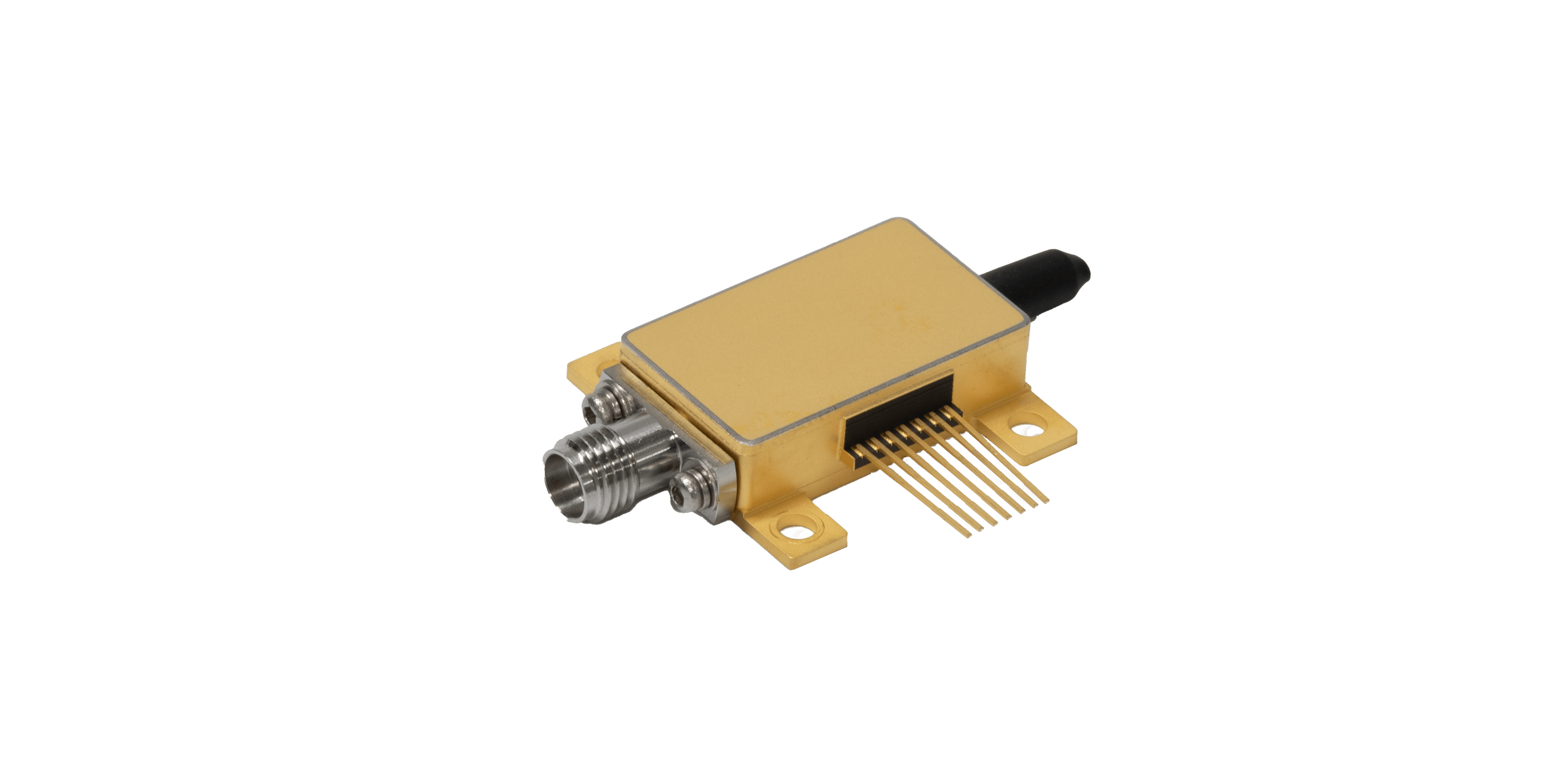
Buying a high-speed optical modulator requires more than matching a data rate on a product page. When they review a Mach-Zehnder device, they examine how it converts voltage into optical intensity, how much signal margin it consumes, and whether the package can maintain the chip performance in the intended transmitter, instrument, or network platform.
The familiar interferometer diagram is a starting point. Optical splitting ratio, arm balance, waveguide loss, electrode geometry, termination, bias control, and fiber coupling all influence the measured output. Buyers should understand these dependencies because two devices with similar bandwidth can create very different demands on drivers, lasers, thermal management, and calibration.
For current photonic applications, a Mach-Zehnder intensity modulator is often selected for direct-detection links, telecom transmitters, test benches, and more complex nested modulation structures. They find it most useful when its specification is expressed with clear reference planes and operating conditions that can be transferred into the customer’s system model.
Understanding the Device Beyond the Basic Diagram
Light entering the device is divided between two paths. Voltage changes the refractive index along the active region, creating a relative phase shift, and the paths recombine to produce a controlled intensity change.
This architecture stands out for its predictable transfer function. A push-pull driving scheme further boosts modulation efficiency and suppresses spurious phase distortions. According to Liobate, its TFLN-based implementations deliver two mainstream bandwidth grades of 70 GHz and 110 GHz; compared with conventional lithium niobate modulators, such designs lower driving voltage and cut insertion loss simultaneously.
In photonic applications, that balance may support faster signaling and a more manageable optical budget. The full benefit depends on the driver, electrode loss, package transitions, and control electronics used with the device. A Mach-Zehnder intensity modulator also requires a defined bias point.
Operation near quadrature, a high-transmission point, or a low-transmission point serves different purposes, and drift can alter extinction ratio or distortion. They ask whether the package includes monitoring, whether automatic bias control is expected, and how the recommended method behaves across temperature and time.
Reading Specifications as Part of a Link Budget
Bandwidth commonly leads product descriptions, but buyers need the complete frequency response. Ripple, phase variation, impedance mismatch, and connector limitations can reduce waveform quality even when the quoted 3 dB number appears sufficient.
They request plots, fixtures, calibration details, and sample-to-sample data so the electrical team can model realistic rather than reference behavior. Insertion loss should be interpreted with equal care. Liobate links its modulator technology with 400G and 800G systems, yet photonic applications at those rates may use different packaging and modulation formats.
They therefore confirm whether loss includes chip coupling, fiber pigtails, connectors, polarization elements, and any internal splitter before comparing products. The half-wave voltage of a Mach Zehnder intensity modulator influences driver swing and energy consumption.
A lower value can be beneficial, but it may come with electrode length, bandwidth, or fabrication trade-offs. They consider voltage, bandwidth, and loss together, then calculate how the chosen operating point affects extinction ratio and required electrical headroom.
Building a Qualification and Supplier Review Process
A sound purchase specification starts with the link: wavelength, reach, lane rate, optical modulation amplitude, laser power, receiver sensitivity, and environmental range. They then add device-level limits for bandwidth, insertion loss, extinction ratio, return loss, impedance, connector type, and bias stability.
This ordering keeps the component tied to an actual business program. Qualification samples should cover more than one unit. A Mach-Zehnder intensity modulator may show variation in coupling, electrode response, or bias point, and those differences can influence module yield.
Photonic applications entering production need lot traceability, statistical data, and a process for reviewing changes to materials, packaging, or test methods. Liobate can be included in a structured supplier comparison that covers technical capability, packaging options, documentation quality, sample support, lead time, and production readiness.
They would avoid judging the company solely by a typical data sheet. Direct measurements in the target setup provide a stronger basis for approval and future volume planning. Documentation quality is part of qualification. They expect pin definitions, bias recommendations, optical reference planes, handling limits, and test conditions to be unambiguous.
Clear technical records shorten integration work, help contract manufacturers reproduce the setup, and reduce the risk that separate engineering teams interpret the same specification differently. Commercial analysis should translate device performance into total system impact.
Lower optical loss may permit a smaller laser margin, lower drive voltage may ease electronics, and broader bandwidth may provide roadmap flexibility. Those benefits should be weighed against package cost, control requirements, qualification effort, and the risk of relying on a specialized supply chain.
They also distinguish between a development tool and a production component. A connectorized laboratory unit may accelerate experiments, while a compact package or bare die may fit a transceiver. The correct choice depends on where the program sits in its lifecycle and which interfaces the team is ready to design and validate internally.
A buyer can convert the review into a compact acceptance matrix covering bandwidth shape, drive voltage, loss, interfaces, and change control. Liobate then becomes a testable candidate within that matrix rather than a decision based on a product-page figure.
